Stained Glass: Difference between revisions
No edit summary |
|||
| (One intermediate revision by the same user not shown) | |||
| Line 15: | Line 15: | ||
[[File:StainedGlassFig1.png|256px|thumb|right]] | [[File:StainedGlassFig1.png|256px|thumb|right]] | ||
For example, “Colorful butterfly in a simple stained glass styled medallion” yielded these possible choices. Next, select the one you like or think will look best in a print. Of these offerings, I think either the one in the upper right or lower left would work well. The one in the upper | For example, “Colorful butterfly in a simple stained glass styled medallion” yielded these possible choices. Next, select the one you like or think will look best in a print. Of these offerings, I think either the one in the upper right or lower left would work well. The one in the upper left is probably too busy to work well in this application and the one lower right is just weird. | ||
One other consideration in making a choice is to consider the number of color families in the image. Colored lithophanes can only be done in one set of related color tones, like red/yellow or shades of blue or green. So, to get two or more tones, two separate parts are needed. | One other consideration in making a choice is to consider the number of color families in the image. Colored lithophanes can only be done in one set of related color tones, like red/yellow or shades of blue or green. So, to get two or more tones, two separate parts are needed. | ||
| Line 49: | Line 49: | ||
[[File:StainedGlassFig6.png|256px|thumb|right]] | [[File:StainedGlassFig6.png|256px|thumb|right]] | ||
Those who are especially observant might notice that there are green regions in both the blue and red/yellow images. That’s because | Those who are especially observant might notice that there are green regions in both the blue and red/yellow images. That’s because it's the plan to blend the two parts to create the green in the final model, even though no green filament will be used in either part. | ||
One final part that is not obvious with this image is that it is usually necessary to mirror the second part before saving it. This is so the two printed parts can be attached back-to-back on their respective flat, build plate sides. | One final part that is not obvious with this image is that it is usually necessary to mirror the second part before saving it. This is so the two printed parts can be attached back-to-back on their respective flat, build plate sides. | ||
Latest revision as of 18:21, 13 July 2024
How to Make a Stained Glass HueForge Lithophane
Tom Lavedas
Introduction
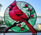
Since I developed the two-part HueForge stained glass colored lithophane technique with the creation of my first model, the Cardinal, people have asked for descriptions of how it’s done and for tutorial videos. Since I have no experience with video creation, I’ve decided to write an article to describe my process.
Step 1: Image Selection
The obvious first step is to select or create the image to be modeled. I have used Image Creator available as a tool in Microsoft’s latest Edge browser, which is not offered as a recommendation. It is just that it is free to use and it’s the one I have been using. The common prompt I have found useful is something like “[Desired object noun/phrase] in a simple stained glass styled medallion”
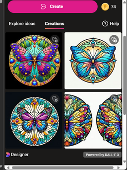
For example, “Colorful butterfly in a simple stained glass styled medallion” yielded these possible choices. Next, select the one you like or think will look best in a print. Of these offerings, I think either the one in the upper right or lower left would work well. The one in the upper left is probably too busy to work well in this application and the one lower right is just weird.
One other consideration in making a choice is to consider the number of color families in the image. Colored lithophanes can only be done in one set of related color tones, like red/yellow or shades of blue or green. So, to get two or more tones, two separate parts are needed.
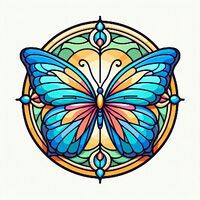
Separating red/yellows from blues or greens is relatively straight forward, but getting the purple in the image at the lower left is more difficult. That is because purple straddles the red and blue color domains. Thus, it might require blending the two color families, one on each half of the two-part print that is needed for this approach. In addition, there are a number of greens in the image. Blending colors is possible of course, but the more blending required, the harder it is to get right. That is because, at this time HueForge does not directly support a visualization of the two halves together. Rather the designer needs to do that in their head and/or with a number of trial-and-error prints. Such visualization is on the app’s developmental roadmap, but will not be available in the near term.
For this discussion, we’ll stick with the image on the upper right.
While not quite as colorful as the one on the lower left, it should be easier to process and to get a good print result with.
Step 2: Photo Processing
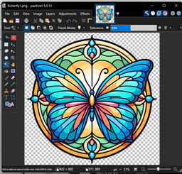
The next step is to preprocess the image in your favorite photo editor. I’m most familiar with paint.net at this writing, though I was recently gifted a copy of the Affinity application.
The first three operations in the photo editor are generally to crop the image to edges of the actual image, then to use the magic wand tool to erase/delete the background outside the boundary of the image and then to save it as a new PNG file type to support the now transparent background. So, it would look like this before starting to separate the colors.
Then the process of isolating one color family starts by painting areas to be removed with white. I find using the paint can tool for most parts to flood the areas surrounded by the black borders to be fairly quick and effective. Use a solid fill with a modest Tolerance setting. Adjust tolerance up or down as needed to keep from painting over colors that are to remain. I also tend to keep all of the boundary outlines in both parts. If they are dark black that is very easy. If they tend to be one or the other of the desired colors, like a dark blue, it can get trickier to set the right tolerance. I have sometimes found it necessary to redraw some boundaries in black, because the original coloring is too close to the one I was eliminating.
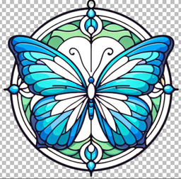
Here is the first part with just the blues and greens remaining and is saved as Butterfly_Part_1.png. All of the yellow, creams and reds have been painted over. I did it bit by bit, though there are ways to set a global erasure. If done that way, introducing a white circle of the right size on a second layer behind the image and then flattening the image is another way that can be faster to fill for a lot of small areas. That approach requires the tolerance of the erasure to be properly managed. I also added a black mounting loop in the image before saving it.
Then use the original PNG image and repeat the process to eliminate the blue parts. In the process it might be advised to use the paint brush tool to eliminate bits of color floating in the middle of newly painted white areas.
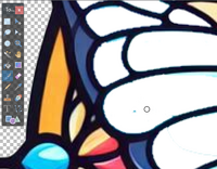
Though they should not affect the quality of the final print, they will add to the print time to lay down tiny dots of filament where they are not needed or wanted. Bits of the color being removed that are immediately adjacent to the dark borders need not be eliminated, though some larger areas might better be removed.
Here is the second part containing the reds and yellows, which share a common color domain.
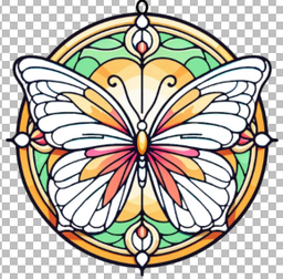
Those who are especially observant might notice that there are green regions in both the blue and red/yellow images. That’s because it's the plan to blend the two parts to create the green in the final model, even though no green filament will be used in either part.
One final part that is not obvious with this image is that it is usually necessary to mirror the second part before saving it. This is so the two printed parts can be attached back-to-back on their respective flat, build plate sides.
The butterfly image used here is perfectly symmetric, so the mirroring is not evident/necessary. In most cases it is very necessary. As was true for the Cardinal model at the top of this article and for the woodpecker example a little further down in here. It’s a step I have sometimes missed right up until I was about to send the job to the printer.
Step 3: HueForge
With the two images processed, it’s now time for HueForge. Here is a good place to start.
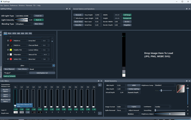
A suggested starting point is to set Lithophane Blending Type at the upper left, the LED Light Type set to Cold White, the Base Layer and Min Depth set to 0.16 mm and just black and natural white in the sliders. I have found that good results are achieved with the layer height set to 0.08 mm, which lowers the print time. I also set the size to 150 by 150 mm once an image is loaded for the same reason, but those are personal choices.
The first slider is a natural filament set to one layer above the base, or 0.24 mm, which is especially useful where the base layer uses a natural (or nearly transparent filament) to minimize any color shifting or muting of the colors. For lithophanes, thinner tends to be better to let the light shine through. So, I suggest working with a Max Height around 1 to 1.5 mm.
Now comes the subjective part. Adding the colors to the image.
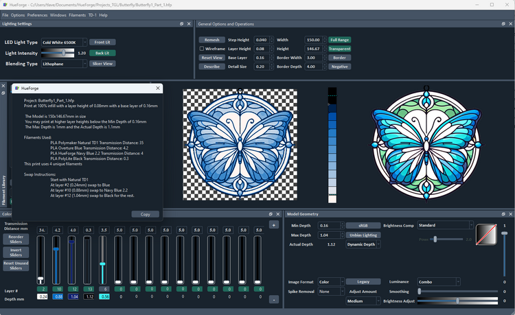
I’ve chosen a blue and a navy blue and tested the addition of an aqua (fifth disabled slider) by enabling and disabling it to see what the effect was. I decided to stay with just the four filaments to fit in my AMS, but adding one more is not that difficult. If you are doing manual swaps, staying with the four filaments reduces the amount of babysitting needed to finish the print.
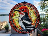
This butterfly image does not have large areas of white. However, if white is desired, there are two options. One is to just leave the areas as white, which are rendered as natural. The other is to specify a lower TD white filament in addition to the natural. In the first case, nothing special needs to be done, but know that the areas will likely be nearly transparent in the final print. If that is not the desired outcome, like in the breast and wing areas of the woodpecker print shown here, the areas to be rendered as white need to be recolored to differentiate them from the ones to be left natural. Paint the areas to be white a very faint gray in the image and then add the lower TD white in HueForge as a few layers above the initial base layer.
Notice the rendered mesh (on the left) does not have the same vibrancy of color as the original. However, my experience with version 0.7.2 is that it doesn’t represent the results of a lithophane perfectly. The actual prints tend to be a bit more colorful than they appear in the program. (I know the developer is aware of this and should address it in a later release, but not with version 0.8.0.)
Save this as a Part 1 project. Then do the same with the image of the second part.
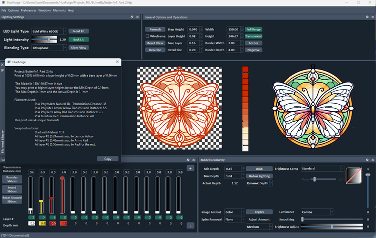
This is what it might look like with yellow and two reds, one low TD (>1) and one midlevel TD (4 – 5). The black is disabled, because I didn’t think it added anything important here. Again, yellow does not appear to fill spaces you might expect to see it in, but it will be there in the actual print. It is a minor failing of the current version of the program. My experience, even with my fairly high TD yellow is that it is much more apparent in the print than it appears here. It is possible a lower TD yellow, like Polylite Savannah Yellow, would give a somewhat more striking color.

A review of the results above has revealed a potential problem that should be addressed before proceeding to printing. Specifically, neither of the parts has green color in it, but as noted earlier there are green areas in the original image. The plan was to color the individual parts in such a way that when joined the colors would blend to give green. However, a number of the areas in this second part are far too red. This is likely to end up too dark and not green, maybe a dark purple or even nearly black.
The solution is to preprocess these areas to lighten them so they present as a yellow, rather than red. The result should look something like this.
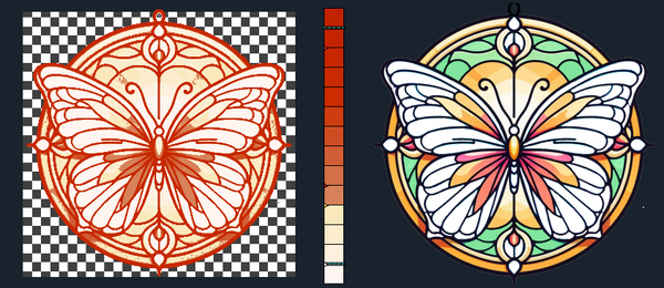
Save this second project, say as Butterfly_Part_2.hfp.
Step 4: Slicing and Printing
I’m assuming readers are experienced with using their slicer of choice and have prepped a HueForge print at least a few times before. So, I’m not going to be too detailed in this part of the process. I’ll just touch on the basics and mention anything that might be unique about preparing these particular print jobs.
I’m using BambuStudio as my slicer and have chosen to load two build plates with the two parts, though they get sliced one at a time. (The warning messages can be ignored.)
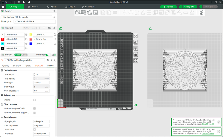
My HueForge specific 0.08 mm layer height slicing profile and procedures are used here. After the first slicing, use the information in the [Project name]_descibe.txt file of the first part to set the filament transitions.
After slicing a second time, it should look something like this.
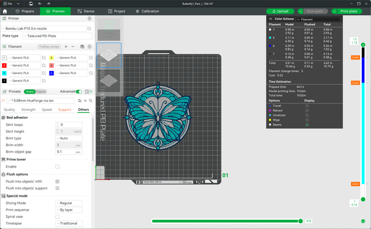
Once sliced, send it to the printer and if you are fortunate enough to have an AMS/MMU and it is loaded with the proper filaments you can go enjoy some other activity for a couple of hours.
When you return it is time to slice and repeat the process for the second part.
Step 5: Assembling
When both parts have been printed, it’s time to assemble the final model. Align the two parts back-to-back and be sparing with the adhesive, especially in the lighter parts. The adhesive will change the colors if it is not behind the darker parts. I use some around the darkest parts and around the very edge to keep the glue from showing. If spread thin and uniformly, it should not show too much.
Here is the final result compared to the original image.
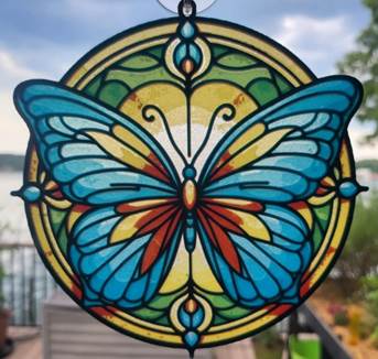
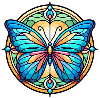
Hope this has helped explain the process sufficient to let you replicate the results with your chosen image. Have fun.