New Color Match Page: Difference between revisions
| (69 intermediate revisions by the same user not shown) | |||
| Line 3: | Line 3: | ||
Thanks to Danny at NeoKoi Prints for these Color Match Crash Course videos: | Thanks to Danny at NeoKoi Prints for these Color Match Crash Course videos: | ||
[https://youtu.be/xBePJlYU3zg?si=ZR0VxOwbRIzlldR1| Lesson 1] | **[https://youtu.be/xBePJlYU3zg?si=ZR0VxOwbRIzlldR1| Lesson 1] | ||
**[https://youtu.be/1qCN3MWJdZM?si=jvBS72YI3n9ZgGkH| Lesson 2] | |||
**[https://youtu.be/cIrGPaCTSg8?si=qfqWMFUnAO7TReIo| Lesson 3] | |||
==What is Color Match?== | |||
Color Match is a Mesh Mode (formerly called a luminance mode) introduced in version 0.8.0 and updated in version 0.9.x. It is a mode that greatly differs from the usual operations of other HueForge mesh modes. Instead of the source image creating a mesh from the image intensity (luminance), in Color Match mode, '''you select''' the colors by dragging them from the image (or the filament library) onto the Mesh Core to create the order of the layers on the mesh. That is, the Mesh Core defines on what layer a color will be put. If you want red in the background, you put it at or near the bottom, if you want blue, you put it there, etc. That is, this mode matches a color to a layer, rather than to a luminance value. | |||
==Overview of Color Match Steps== | |||
The following are steps briefly describing how to use the Color Match mode to develop a project in HueForge. | |||
1. Load the image into HueForge and select Color Match from the Mesh Mode drop down menu. | |||
2. Make sure the Mesh Core just to the left of the image is highlighted by clicking on it, if necessary. | |||
3. ***Important:*** Ctrl-drag colors from the image onto the Mesh Core at the places desired in the stack of colors. This is commonly done from darkest to lightest colors. Near matching actual filaments can be added to the Mesh Core, though this is not generally the best practice. (Note that other orders sometimes work better - takes practice.) | |||
4. It is often necessary to then adjust the TD values of the colors (not filaments, if used) on the Mesh Core to enable better blending of colors into intermediate shades. Hover over the color flag and press T to toggle from layer number to/from TD values. The default for a color is a TD = 1. Use the scroll wheel or arrow keys to adjust the TD. | |||
4. Once the preview image at the left is acceptably colored, switch to the Color Core by clicking on it, just to the right of the preview pane. | |||
5. Select filaments matching (or resembling) the color on the Mesh Core and place them on the Color Core at the appropriate layer. | |||
6. Adjust the layer heights of filaments (Color Core) and/or colors (Mesh Core) to help achieve desired results. | |||
7. Save the project for printing. Reference the project's describe.txt file for how to specify the colors in your slicer (must be added manually). | |||
Details for these steps are provided with examples below. | |||
==Understanding the Color Core and the Mesh Core== | ==Understanding the Color Core and the Mesh Core== | ||
One of the biggest differences in this mode is that there are two cores between the image and preview panes. The one to the left is the standard Color Core, while | One of the biggest differences in this mode is that there are two cores between the image and preview panes. The one to the left is the standard Color Core which defines the model to be printed, while the second one is the Mesh Core to its right with a number of controls between the two. Learning the purpose and operation of the Mesh Core is fundamental to using the Color Match mode successfully. Making full use of this mode takes some practice but once grasped it opens up a whole realm of possibilities the other modes cannot match. | ||
[[File: Color_Match_Mode.png|500px|center]] | [[File: Color_Match_Mode.png|500px|center]] | ||
Color Match is initiated from the appropriate toolbar by selecting that option from the Mesh Mode drop-down menu. | Most of the controls that were in docks in previous versions of HueForge are now housed in toolbars at the top or bottom of the version 0.9+ application window. Likewise, Color Match is initiated from the appropriate toolbar by selecting that option from the Mesh Mode drop-down menu. | ||
[[File: Mesh_Mode_Dropdown.png|250px|center]] | [[File: Mesh_Mode_Dropdown.png|250px|center]] | ||
===Mesh Core=== | To help understand the two cores, let's work through two example prints, one very simple and one advanced. | ||
===A Simple Example=== | |||
The process is in two stages: populating the Mesh Core with the image colors (and/or filament colors) and then populating the Color Core with filament colors. | |||
====Mesh Core==== | |||
After loading your image, assembling colors on the Mesh Core is the essential first step in the Color Match workflow. For the purpose of illustration, let's start with a very simple image that might be possible in another mode just to illustrate the Color Match workflow. | |||
[[File: Pixel_Tree.png|250px|center|A Pixelated Tree Image]] | |||
Click this link to access the example image and download or drag it into HueForge: [[Media:Pixel_Tree.png]] | |||
Once loaded into HueForge, it will appear in the default grayscale of the Standard Mesh Mode. | |||
[[File: Simple_Example_Image.png| The Mesh Core (cyan surround) |thumb|500px|center]] | |||
Once the Color Match Mesh mode is selected it is time to get colors from the image. This is easily done by Ctrl-dragging using the cursor (Cmd-drag in MacOS) from the image onto the Mesh Core. Filaments that are a color match to the colors in the image can also be dragged from the library to the Mesh Core, though some image derived colors help to improve the blending of color in the final model. This is especially true for areas where colors change gradually from one shade to another. | |||
When the Mesh Core is active (surrounded be a cyan box), the image preview on the left reflects the model mesh as defined by the Mesh Core. Below is a short example of dragging a color (while holding the Ctrl or Cmd key) from the image to the mesh. | |||
[[File: A_Color_Drag.mp4|500px|center|thummb|Drag a Green from the Image.]] | |||
Colors derived from the source image and placed on the Mesh Core are normally blended in the same manner as they would if they were "real" filaments. Then the program seeks to match the resulting spectrum of colors to the filament colors that you add to the Color Core later in the workflow (or sliders, if using, though the sliders are no longer fundamental in versions after 0.9.0). Note that there is little or no blending for this simple image because the colors were specifically made flat. | |||
Since the Mesh Core allows you to build the filament painting's mesh by picking colors and placing them at any layer on the core, colors placed on the lower layers of the mesh core will be laid down first (for example, the background of an image) and then they blend upward as you add colors to the Mesh Core. | |||
In this simple example we need to place the brown, green and blue somewhere between the black lower and white upper colors to replace the original two grays and in one more place. | |||
[[File:Simple_Mesh_Loaded.png|500px|center|thumb|Simple Image Mesh]] | |||
Several things to note in the illustration above are that the total height of the model is much lower than the initial height, that the black layers are reduced to a minimum and that the Mesh Core preview is very nearly identical to the input image. One thing that is not obvious, but true, is that the highest color (white filament) is not contributing to the image at all. If you compare the reported Mesh Height below the preview at 1.12 mm to the topmost color flag on the Mesh Core at 1.6 mm, it becomes apparent. Because that is the case, HueForge does not include it in the output mesh. | |||
The reason the total height of the model was reduced is that adding more layers failed to change the blended shades of those colors. That is, the colors became saturated and adding more layers only adds more print time without any change in the appearance of the final print (as illustrated in the preview on the left). The way saturation is shown is by an equal sign turned vertically on the core at the layer where the saturation begins and subsequent saturated layers. As mentioned, saturated layers at the top of the print are ignored (i.e. not included in the model mesh). | |||
Generally having saturated layers on the cores is to be avoided as they have little if any impact on the results. However, there are a few times where saturated layers are useful. One is when it is desired to block blending of lower levels into the colors above. For example, a well saturated black between a red and a blue can keep purple shades from appearing in the print. Likewise, a saturated white to keep dark tones from creeping into bright pastel colors. Another time it is useful is if a very thick print is intended for effect. Just know that the program stops trying to match colors after the first layer of saturated color. | |||
Another important point to note is that the TD value of colors derived from an image onto the Mesh Core is one (1) by default. Such colors saturate in just a few layers. It is very often valuable to adjust these values up (or down) to enable more gradual transitions from one color/shade to another to get the best results. This will become more evident in the next, more complicated example. The values are adjusted by hovering over a color flag and pressing the T key or right-clicking to open a popup menu and selecting the "Show TD (t)" menu item. Then use the scroll ring or up/down arrow keys to change it. Normally the increment is 0.5 per click or 0.2 if the Shift key is held. This is true UNLESS you drop an image color onto a '''filament''' - not layer - that is already on the Mesh Core (like one of your default filaments) then it keeps the TD assigned to that filament. | |||
Once the Mesh Core preview is satisfactory, operation switches to the Color Core. | |||
====Color Core==== | |||
The next step in the process after setting up the Mech Core is to move to the Color Core, by clicking on it or by pressing the green arrow button at the bottom between the two cores. Do not be surprised by the preview that results, as it is likely to be in grayscale, since it only has your default filament set on it at this point. | |||
[[File: Simple_Example_CC_Start.png| Default Color Core Preview |thumb|500px|center]] | |||
The selection of filaments can be straightforward for this example, though that is not always the case. It depends on how complicated the image is and how many colors are present. For this simple image the idea is to replace the default filaments with colors present on the Mesh Core. So pick a green, brown and blue similar to the ones on the image and drop them on to the Color Core at locations opposite the ones on the Mesh Core. Start with colors you have in your Owned library, which should be easy for this four-color image. More complex images are likely to require some compromises as it isn't possible (or necessary) to own all the colors and shades of filament. In such cases, there are techniques that work to expand the available pallet of colors, like blending a color over black to darken the shade or adding a white over a color to lighten it. Keep those concepts in mind while building a Color Core stack. | |||
If you are having trouble picking a color, the nearest filament color can be found by hovering the cursor over a color (on the Mesh Core or on the image), right-click and use the "Find Closest Filament" item in the popup menu (as shown below). | |||
[[File: Simple_Example_Find_Filament.png| Find Closest Filament |thumb|500px|center]] | |||
This sorts the Owned And Unowned filament library lists to put matching colors in descending order from closest color, so that a selection can be easily made. Note that it is sometimes useful to look at the Unowned list, if you are not satisfied with any of the Owned colors. You can always run a trial to see if buying the unowned color is worth considering. | |||
Once you have made your color selections, your preview should look something like this. | |||
[[File: Simple_Image_Color_Core.png| Loaded Color Core Preview |thumb|500px|center]] | |||
And there you have it a finished Color Match project ready to print. It isn't likely you'd want to print this one, but that is the bare bones process for a color match. | |||
Having gotten this far, you can choose to try a more complex image that is probably best attempted with Color Match Mesh Mode. | |||
===An Advanced Example=== | |||
====Mesh Core==== | |||
Now let's advance to an image that would be nearly impossible to render satisfactorily in any of the other Mesh Modes, that is the image from the "Van Gogh Style Field.hfp" example in the HueForge/Tools folder. | |||
[[File: Van Gogh Style Field.webp|250px|center]] | |||
Click this link to access the example image and download or drag it into HueForge: [[Media: Van Gogh Style Field.webp]] | |||
('''Note:''' This image is from the project by that name in the HueForge/Projects folder but would need to be exported from it since all the example projects store their images internal to the project file.) | |||
The | [[File: Von_Gogh_Example_Image.png| The Mesh Core (red surround) |thumb|500px|center]] | ||
To further illustrate this process, the image, taken from the HueForge/Projects folder is shown here with black and white filaments (at the top and bottom, designated with five sided outlines) and six image derived colors on the Mesh Core (designated by six sided outlines). It is meant to show a Mesh Core as one might begin to define the color layers there. Note that the preview image on the left is only a representation of the image resulting from the "fake" filaments shown. A preview of the likely print | To further illustrate this process, the image, taken from the HueForge/Projects folder is shown here with black and white filaments (at the top and bottom, designated with five sided outlines) and six image derived colors on the Mesh Core (designated by six sided outlines). It is meant to show a Mesh Core as one might begin to define the color layers there. Note that the preview image on the left is only a representation of the image resulting from the "fake" filaments shown. A preview of the likely print result is developed in the Color Core part of the workflow that follows. | ||
[[File:Mesh_Core.png|500px|center]] | [[File: Mesh_Core.png| Mesh Core Preview |500px|thumb|center]] | ||
When you select the colors and put them on the mesh core, you’re actually changing the shape of the mesh. You can validate this by turning on Wireframe, zooming into your mesh, and moving sliders on the mesh core up and down (make sure mesh core is selected). This helps to show how to build your mesh. Dark to light or light to dark, where to put colors, etc. | |||
[[File:Mesh_Core_TDs.png|500px|center]] | An important distinction to note is that the TD values of an image derived color is 1 by default. It is very often useful, even necessary, to adjust this value to better match actual filaments to be applied to the Color Core later in the process. Pressing T while hovering over a color flag shows the value. Either scroll up/down or use the up/down arrow keys to change the values in increments of 0.5. Hold the Ctrl key to change the values in steps of 0.2. | ||
Specifically, the example shown above is shown below with all the TD values shown, as revealed by pressing the green TD button (toggles) to the left of the Mesh Core near its bottom. (You might need to click on the image shown here once to open a page with the stored file and then again on that image to get to get a full-size image to see the detail. Then back up twice to get back to this page.) | |||
[[File:Mesh_Core_TDs.png| Filament TDs Displayed |500px|thumb|center]] | |||
Take care to change ''''only'''' the image colors and not the values of any actual filament on either of the cores. If that happens, save your work, leave HueForge while rejecting any filament library saves and then reopen your project to avoid permanently altering the values unintentionally. | |||
Though there are clearly some shortcomings at this point in the development, such as the miscolored flowers and clouds and some missing reddish-brown details, this example illustrates the basic function of the Mesh Core. | Though there are clearly some shortcomings at this point in the development, such as the miscolored flowers and clouds and some missing reddish-brown details, this example illustrates the basic function of the Mesh Core. | ||
| Line 49: | Line 139: | ||
Once the Mesh Core preview is satisfactory, operation switches to the Color Core. | Once the Mesh Core preview is satisfactory, operation switches to the Color Core. | ||
===Color Core=== | ====Color Core==== | ||
[[File: Start_Color_Core.png| Color Core Preview |thumb|500px|center]] | |||
Once you have your mesh core looking good, the next step is to select filament colors that match or approximate the corresponding colors found on the Mesh Core. First, select the color core (double click). Then find colors that match your mesh core and add them to your color core by dragging them from the filament library. Probably best to select primary, solid colors to start. Blacks, reds, whites, etc, paying attention to their TD’s while doing this. Next, consider colors to make blends, i.e. yellows and blues for a green. That kind of thing. Note: It’s not uncommon to have many more colors on the Mesh Core than filaments on the Color Core. Prints with a 3:1 mesh:filament ratios are not out of the question. Remember, the Mesh Core defines where colors are matched in the mesh. The Color Core defines the colors. | |||
Filaments can come directly by eye from your Owned library filaments by dragging to the Color Core, as with other modes. Or they can be matched to the colors previously placed on the Mesh Core by right-clicking on the filament flag (or a two-finger press on a track pad or an Apple mouse) and selecting Find Closest Filament. This sorts the filament Owned and Unowned library lists putting the best matching filament colors at the top of each list. Colors on the image can also be used in much the same manner by right-clicking at a location on the image. | |||
The | The preview image on the left will not change to reflect the selected colors until the Color Core is selected by clicking on it or using the arrow control button at the bottom right of the core. It is not entirely bad to wait to do this until all or most of the first set of colors are in place on the core, because the image will become falsely colored with each partial set of colors. This can be downright scary to watch. For example, this is what it would look like if the first dark blue filament selection was used to replace the first default gray filament | ||
[[File: Color_Core_One_Color.png|One Color on the Color Core|thumb|500px|center]] | |||
Delaying the selection until an initial set of the colors is in place results in a more pleasing first impression of the print preview that results. For example, this example might look something like this with seven filaments placed in appropriate places on the Color Core. | |||
[[File: Colors_Placed_on_Color_Core.png| Initial Color Set |thumb|500px|center]] | |||
While it is not perfect, this is a good start. Not too bad for just seven filament colors. It needs a reddish-brown, some work on the colors in the clouds, and refinement of the greens and yellows. Accomplishing this might require an increase in the Blend Depth and/or reduction of the layer height to accommodate more colors. | |||
Here is an attempt with just seven filament colors with 0.04 mm layer heights. Note that this also employes the Bright Enhance 1 Brightness Compensation with a weighting of 1.4 as well as the Fast Spike Removal. To limit the number of different filaments the white was reused to provide lighter versions of several colors. Using a yellow in multiple places can also help to blend greens into lime colors and reds into oranges. This approach widens the color pallet available from a limited number of filaments | |||
[[File: Color_Match_0.04mm.png| Initial Color Set |thumb|500px|center]] | |||
So, is this an exact replication of the original image? Obviously not. But at some point in the development, it might be best to stop looking at the original and just decide whether the preview represents the print you would be pleased to have. | |||
==Final Tips and Techniques== | |||
# While doing the final editing it is often useful to add a filament just to see how it works in the composition. In the event it doesn't work, the filament can be disabled by hovering over its flag on the Color Core and pressing the spacebar or right-click and select the Disable or Delete Slider option. Hitting the delete key also works to delete the filament. The disable function can be toggled on and off by pressing the spacebar to allow easy comparison. | |||
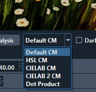
# The Matching algorithm is adjustable in a drop down at the bottom of the image (right) pane. (A development version might move it to the Mesh Mode tool bar.) It is initially in the CIELAB 2 CM setting which is often the best selection. Other selections are as shown. It is useful to try the options reasonably early in development to determine which is best for your particular image. [[File: Color_Match_Dialog.png|200px|center]] | |||
# Images with soft gradient colors benefit a lot by putting more colors off of the image on the Mesh Core. | |||
#To get a good color match, it can be beneficial to insert a LOT of individual image colors on the Mesh Core for some images. You do not need to copy them all over to the Color Core and can often simplify them to a lot fewer colors. The purpose of the extra colors on the Mesh Core is just to aid with strong matching. | |||
# When working on the Color Core, after setting up the Mesh Core, lay out the filaments in ways that approximates the spectrum of colors on the Mesh Core. In doing that, remember it is possible to blend a white over a primary color to blend toward a pastel color. This can help limit the number of filaments needed and greatly expand the pallet of colors available. | |||
# Vertical equal signs in a core means that color is saturate at that layer. If it is in the Mesh Core, that layer will not be used to match colors in the preview and if they are at the top of the mesh the model will not include the upper saturated layers, unless the lower layers are disabled (Right Click->Disable Layer). If it is in the Color Core, the blending of that color is not changed. | |||
Latest revision as of 13:04, 31 December 2025
Video Work Along Tutorials (0.9+)
Thanks to Danny at NeoKoi Prints for these Color Match Crash Course videos:
What is Color Match?
Color Match is a Mesh Mode (formerly called a luminance mode) introduced in version 0.8.0 and updated in version 0.9.x. It is a mode that greatly differs from the usual operations of other HueForge mesh modes. Instead of the source image creating a mesh from the image intensity (luminance), in Color Match mode, you select the colors by dragging them from the image (or the filament library) onto the Mesh Core to create the order of the layers on the mesh. That is, the Mesh Core defines on what layer a color will be put. If you want red in the background, you put it at or near the bottom, if you want blue, you put it there, etc. That is, this mode matches a color to a layer, rather than to a luminance value.
Overview of Color Match Steps
The following are steps briefly describing how to use the Color Match mode to develop a project in HueForge.
1. Load the image into HueForge and select Color Match from the Mesh Mode drop down menu.
2. Make sure the Mesh Core just to the left of the image is highlighted by clicking on it, if necessary.
3. ***Important:*** Ctrl-drag colors from the image onto the Mesh Core at the places desired in the stack of colors. This is commonly done from darkest to lightest colors. Near matching actual filaments can be added to the Mesh Core, though this is not generally the best practice. (Note that other orders sometimes work better - takes practice.)
4. It is often necessary to then adjust the TD values of the colors (not filaments, if used) on the Mesh Core to enable better blending of colors into intermediate shades. Hover over the color flag and press T to toggle from layer number to/from TD values. The default for a color is a TD = 1. Use the scroll wheel or arrow keys to adjust the TD.
4. Once the preview image at the left is acceptably colored, switch to the Color Core by clicking on it, just to the right of the preview pane.
5. Select filaments matching (or resembling) the color on the Mesh Core and place them on the Color Core at the appropriate layer.
6. Adjust the layer heights of filaments (Color Core) and/or colors (Mesh Core) to help achieve desired results.
7. Save the project for printing. Reference the project's describe.txt file for how to specify the colors in your slicer (must be added manually).
Details for these steps are provided with examples below.
Understanding the Color Core and the Mesh Core
One of the biggest differences in this mode is that there are two cores between the image and preview panes. The one to the left is the standard Color Core which defines the model to be printed, while the second one is the Mesh Core to its right with a number of controls between the two. Learning the purpose and operation of the Mesh Core is fundamental to using the Color Match mode successfully. Making full use of this mode takes some practice but once grasped it opens up a whole realm of possibilities the other modes cannot match.

Most of the controls that were in docks in previous versions of HueForge are now housed in toolbars at the top or bottom of the version 0.9+ application window. Likewise, Color Match is initiated from the appropriate toolbar by selecting that option from the Mesh Mode drop-down menu.

To help understand the two cores, let's work through two example prints, one very simple and one advanced.
A Simple Example
The process is in two stages: populating the Mesh Core with the image colors (and/or filament colors) and then populating the Color Core with filament colors.
Mesh Core
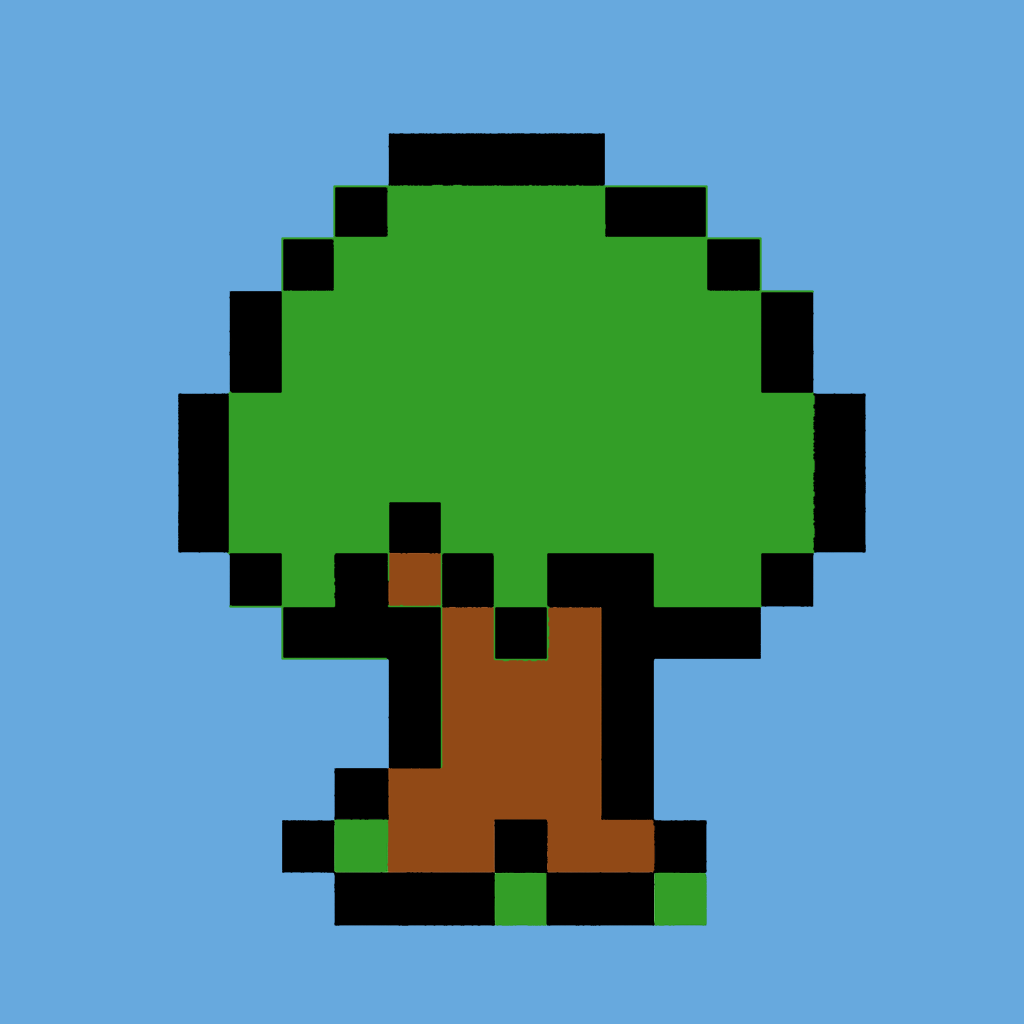
After loading your image, assembling colors on the Mesh Core is the essential first step in the Color Match workflow. For the purpose of illustration, let's start with a very simple image that might be possible in another mode just to illustrate the Color Match workflow.
Click this link to access the example image and download or drag it into HueForge: Media:Pixel_Tree.png
Once loaded into HueForge, it will appear in the default grayscale of the Standard Mesh Mode.

Once the Color Match Mesh mode is selected it is time to get colors from the image. This is easily done by Ctrl-dragging using the cursor (Cmd-drag in MacOS) from the image onto the Mesh Core. Filaments that are a color match to the colors in the image can also be dragged from the library to the Mesh Core, though some image derived colors help to improve the blending of color in the final model. This is especially true for areas where colors change gradually from one shade to another.
When the Mesh Core is active (surrounded be a cyan box), the image preview on the left reflects the model mesh as defined by the Mesh Core. Below is a short example of dragging a color (while holding the Ctrl or Cmd key) from the image to the mesh.
Colors derived from the source image and placed on the Mesh Core are normally blended in the same manner as they would if they were "real" filaments. Then the program seeks to match the resulting spectrum of colors to the filament colors that you add to the Color Core later in the workflow (or sliders, if using, though the sliders are no longer fundamental in versions after 0.9.0). Note that there is little or no blending for this simple image because the colors were specifically made flat.
Since the Mesh Core allows you to build the filament painting's mesh by picking colors and placing them at any layer on the core, colors placed on the lower layers of the mesh core will be laid down first (for example, the background of an image) and then they blend upward as you add colors to the Mesh Core.
In this simple example we need to place the brown, green and blue somewhere between the black lower and white upper colors to replace the original two grays and in one more place.

Several things to note in the illustration above are that the total height of the model is much lower than the initial height, that the black layers are reduced to a minimum and that the Mesh Core preview is very nearly identical to the input image. One thing that is not obvious, but true, is that the highest color (white filament) is not contributing to the image at all. If you compare the reported Mesh Height below the preview at 1.12 mm to the topmost color flag on the Mesh Core at 1.6 mm, it becomes apparent. Because that is the case, HueForge does not include it in the output mesh.
The reason the total height of the model was reduced is that adding more layers failed to change the blended shades of those colors. That is, the colors became saturated and adding more layers only adds more print time without any change in the appearance of the final print (as illustrated in the preview on the left). The way saturation is shown is by an equal sign turned vertically on the core at the layer where the saturation begins and subsequent saturated layers. As mentioned, saturated layers at the top of the print are ignored (i.e. not included in the model mesh).
Generally having saturated layers on the cores is to be avoided as they have little if any impact on the results. However, there are a few times where saturated layers are useful. One is when it is desired to block blending of lower levels into the colors above. For example, a well saturated black between a red and a blue can keep purple shades from appearing in the print. Likewise, a saturated white to keep dark tones from creeping into bright pastel colors. Another time it is useful is if a very thick print is intended for effect. Just know that the program stops trying to match colors after the first layer of saturated color.
Another important point to note is that the TD value of colors derived from an image onto the Mesh Core is one (1) by default. Such colors saturate in just a few layers. It is very often valuable to adjust these values up (or down) to enable more gradual transitions from one color/shade to another to get the best results. This will become more evident in the next, more complicated example. The values are adjusted by hovering over a color flag and pressing the T key or right-clicking to open a popup menu and selecting the "Show TD (t)" menu item. Then use the scroll ring or up/down arrow keys to change it. Normally the increment is 0.5 per click or 0.2 if the Shift key is held. This is true UNLESS you drop an image color onto a filament - not layer - that is already on the Mesh Core (like one of your default filaments) then it keeps the TD assigned to that filament.
Once the Mesh Core preview is satisfactory, operation switches to the Color Core.
Color Core
The next step in the process after setting up the Mech Core is to move to the Color Core, by clicking on it or by pressing the green arrow button at the bottom between the two cores. Do not be surprised by the preview that results, as it is likely to be in grayscale, since it only has your default filament set on it at this point.

The selection of filaments can be straightforward for this example, though that is not always the case. It depends on how complicated the image is and how many colors are present. For this simple image the idea is to replace the default filaments with colors present on the Mesh Core. So pick a green, brown and blue similar to the ones on the image and drop them on to the Color Core at locations opposite the ones on the Mesh Core. Start with colors you have in your Owned library, which should be easy for this four-color image. More complex images are likely to require some compromises as it isn't possible (or necessary) to own all the colors and shades of filament. In such cases, there are techniques that work to expand the available pallet of colors, like blending a color over black to darken the shade or adding a white over a color to lighten it. Keep those concepts in mind while building a Color Core stack.
If you are having trouble picking a color, the nearest filament color can be found by hovering the cursor over a color (on the Mesh Core or on the image), right-click and use the "Find Closest Filament" item in the popup menu (as shown below).

This sorts the Owned And Unowned filament library lists to put matching colors in descending order from closest color, so that a selection can be easily made. Note that it is sometimes useful to look at the Unowned list, if you are not satisfied with any of the Owned colors. You can always run a trial to see if buying the unowned color is worth considering.
Once you have made your color selections, your preview should look something like this.

And there you have it a finished Color Match project ready to print. It isn't likely you'd want to print this one, but that is the bare bones process for a color match.
Having gotten this far, you can choose to try a more complex image that is probably best attempted with Color Match Mesh Mode.
An Advanced Example
Mesh Core
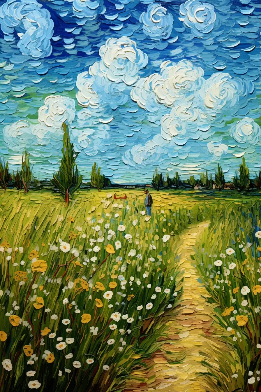
Now let's advance to an image that would be nearly impossible to render satisfactorily in any of the other Mesh Modes, that is the image from the "Van Gogh Style Field.hfp" example in the HueForge/Tools folder.

Click this link to access the example image and download or drag it into HueForge: Media: Van Gogh Style Field.webp
(Note: This image is from the project by that name in the HueForge/Projects folder but would need to be exported from it since all the example projects store their images internal to the project file.)

To further illustrate this process, the image, taken from the HueForge/Projects folder is shown here with black and white filaments (at the top and bottom, designated with five sided outlines) and six image derived colors on the Mesh Core (designated by six sided outlines). It is meant to show a Mesh Core as one might begin to define the color layers there. Note that the preview image on the left is only a representation of the image resulting from the "fake" filaments shown. A preview of the likely print result is developed in the Color Core part of the workflow that follows.

When you select the colors and put them on the mesh core, you’re actually changing the shape of the mesh. You can validate this by turning on Wireframe, zooming into your mesh, and moving sliders on the mesh core up and down (make sure mesh core is selected). This helps to show how to build your mesh. Dark to light or light to dark, where to put colors, etc.
An important distinction to note is that the TD values of an image derived color is 1 by default. It is very often useful, even necessary, to adjust this value to better match actual filaments to be applied to the Color Core later in the process. Pressing T while hovering over a color flag shows the value. Either scroll up/down or use the up/down arrow keys to change the values in increments of 0.5. Hold the Ctrl key to change the values in steps of 0.2.
Specifically, the example shown above is shown below with all the TD values shown, as revealed by pressing the green TD button (toggles) to the left of the Mesh Core near its bottom. (You might need to click on the image shown here once to open a page with the stored file and then again on that image to get to get a full-size image to see the detail. Then back up twice to get back to this page.)

Take care to change 'only' the image colors and not the values of any actual filament on either of the cores. If that happens, save your work, leave HueForge while rejecting any filament library saves and then reopen your project to avoid permanently altering the values unintentionally.
Though there are clearly some shortcomings at this point in the development, such as the miscolored flowers and clouds and some missing reddish-brown details, this example illustrates the basic function of the Mesh Core.
Once the Mesh Core preview is satisfactory, operation switches to the Color Core.
Color Core

Once you have your mesh core looking good, the next step is to select filament colors that match or approximate the corresponding colors found on the Mesh Core. First, select the color core (double click). Then find colors that match your mesh core and add them to your color core by dragging them from the filament library. Probably best to select primary, solid colors to start. Blacks, reds, whites, etc, paying attention to their TD’s while doing this. Next, consider colors to make blends, i.e. yellows and blues for a green. That kind of thing. Note: It’s not uncommon to have many more colors on the Mesh Core than filaments on the Color Core. Prints with a 3:1 mesh:filament ratios are not out of the question. Remember, the Mesh Core defines where colors are matched in the mesh. The Color Core defines the colors.
Filaments can come directly by eye from your Owned library filaments by dragging to the Color Core, as with other modes. Or they can be matched to the colors previously placed on the Mesh Core by right-clicking on the filament flag (or a two-finger press on a track pad or an Apple mouse) and selecting Find Closest Filament. This sorts the filament Owned and Unowned library lists putting the best matching filament colors at the top of each list. Colors on the image can also be used in much the same manner by right-clicking at a location on the image.
The preview image on the left will not change to reflect the selected colors until the Color Core is selected by clicking on it or using the arrow control button at the bottom right of the core. It is not entirely bad to wait to do this until all or most of the first set of colors are in place on the core, because the image will become falsely colored with each partial set of colors. This can be downright scary to watch. For example, this is what it would look like if the first dark blue filament selection was used to replace the first default gray filament

Delaying the selection until an initial set of the colors is in place results in a more pleasing first impression of the print preview that results. For example, this example might look something like this with seven filaments placed in appropriate places on the Color Core.

While it is not perfect, this is a good start. Not too bad for just seven filament colors. It needs a reddish-brown, some work on the colors in the clouds, and refinement of the greens and yellows. Accomplishing this might require an increase in the Blend Depth and/or reduction of the layer height to accommodate more colors.
Here is an attempt with just seven filament colors with 0.04 mm layer heights. Note that this also employes the Bright Enhance 1 Brightness Compensation with a weighting of 1.4 as well as the Fast Spike Removal. To limit the number of different filaments the white was reused to provide lighter versions of several colors. Using a yellow in multiple places can also help to blend greens into lime colors and reds into oranges. This approach widens the color pallet available from a limited number of filaments

So, is this an exact replication of the original image? Obviously not. But at some point in the development, it might be best to stop looking at the original and just decide whether the preview represents the print you would be pleased to have.
Final Tips and Techniques
- While doing the final editing it is often useful to add a filament just to see how it works in the composition. In the event it doesn't work, the filament can be disabled by hovering over its flag on the Color Core and pressing the spacebar or right-click and select the Disable or Delete Slider option. Hitting the delete key also works to delete the filament. The disable function can be toggled on and off by pressing the spacebar to allow easy comparison.
- The Matching algorithm is adjustable in a drop down at the bottom of the image (right) pane. (A development version might move it to the Mesh Mode tool bar.) It is initially in the CIELAB 2 CM setting which is often the best selection. Other selections are as shown. It is useful to try the options reasonably early in development to determine which is best for your particular image.
- Images with soft gradient colors benefit a lot by putting more colors off of the image on the Mesh Core.
- To get a good color match, it can be beneficial to insert a LOT of individual image colors on the Mesh Core for some images. You do not need to copy them all over to the Color Core and can often simplify them to a lot fewer colors. The purpose of the extra colors on the Mesh Core is just to aid with strong matching.
- When working on the Color Core, after setting up the Mesh Core, lay out the filaments in ways that approximates the spectrum of colors on the Mesh Core. In doing that, remember it is possible to blend a white over a primary color to blend toward a pastel color. This can help limit the number of filaments needed and greatly expand the pallet of colors available.
- Vertical equal signs in a core means that color is saturate at that layer. If it is in the Mesh Core, that layer will not be used to match colors in the preview and if they are at the top of the mesh the model will not include the upper saturated layers, unless the lower layers are disabled (Right Click->Disable Layer). If it is in the Color Core, the blending of that color is not changed.
